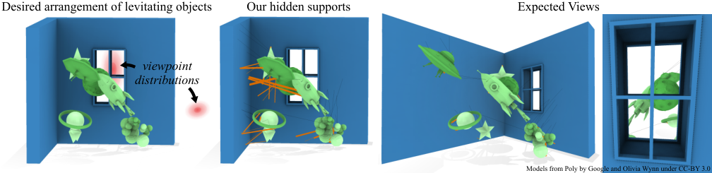
Walk into a gallery, museum, or themed room and objects appear to float — a rocket, a whale skeleton, playing cards, dresses overhead. Without visible struts breaking the illusion, the scene feels magical. This is physical storytelling through space: the arrangement of levitating objects is the narrative.
Making objects truly float is easy with thick, obvious supports. Making them float invisibly is hard. Every rigid piece must balance force and torque under gravity, but thin wires only resist tension and thick rods compete for attention. Remove too much structure and the scene collapses; leave too much and the magic is gone.
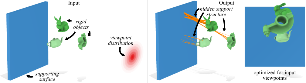
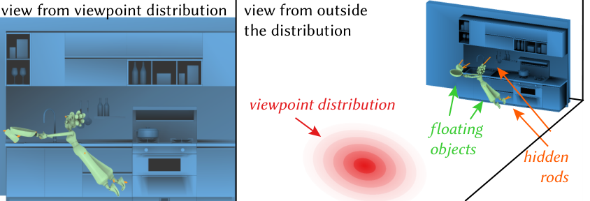
We model hidden support generation as topology optimization on a ground structure — a dense graph of candidate rods and wires between Poisson-disk sample points on each rigid object and a fixed support surface (wall, ceiling, or floor). A convex linear program selects a sparse subset of edges that holds every object in force and torque equilibrium while minimizing material volume and visibility from a user-specified distribution of viewpoints.
Rods resist tension, compression, and bending (wooden dowels, steel beams). Wires resist tension only (fishing line, cable). The optimizer assigns each candidate edge a non-negative cross-sectional area; most areas end up exactly zero, leaving only the supports you actually build.
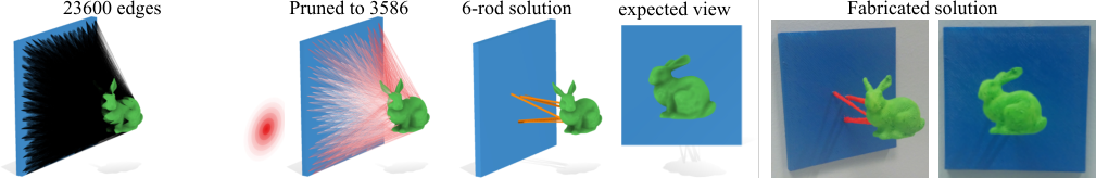
We connect all pairs of sample points between different objects and the support surface, label each edge as a candidate rod or wire, then prune edges that self-penetrate, intersect scene geometry, or have exceptionally high visibility coefficients. Pruning often shrinks the graph by 10× before the linear program runs.
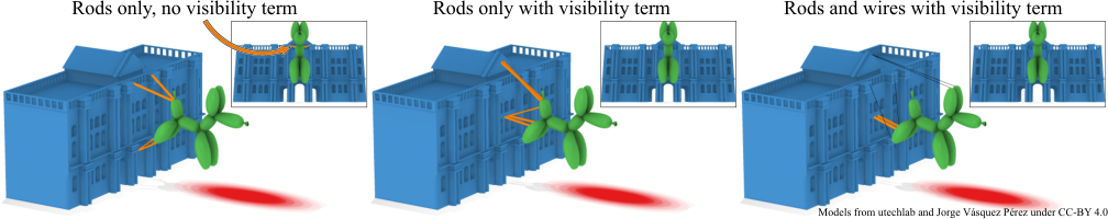
For each rod, we estimate expected visibility by Monte Carlo sampling over the viewpoint distribution. From each sample viewpoint $\mathbf{e}$, we cast rays along the rod and check whether the segment is occluded by scene geometry. The visible contribution is weighted by solid angle — the same physical rod appears smaller when viewed end-on or from farther away.
We approximate the rod as a line for visibility (rods are thin relative to the scene), accounting for foreshortening: a rod viewed at a glancing angle subtends less apparent area than one seen broadside. Precomputing a per-edge coefficient $g_{ij}$ makes squared visibility linear in cross-sectional area: $a_{ij} g_{ij}^2$. Wires are treated as invisible ($g_{ij}=0$) and skip this step.
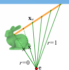
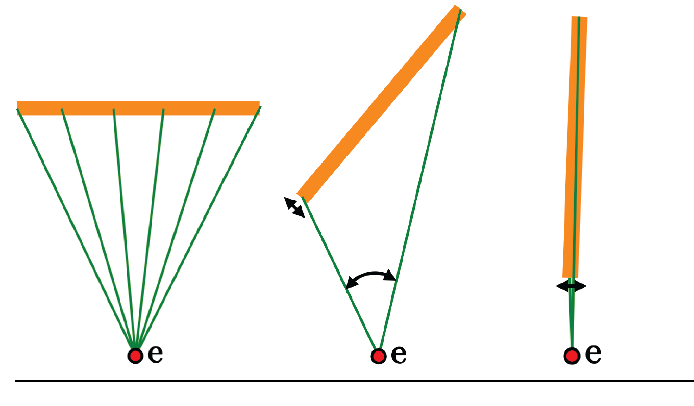
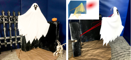
Here $r(\mathbf{e},\mathbf{x}) = 0$ if the segment from viewpoint $\mathbf{e}$ to point $\mathbf{x}$ hits the scene, and $1$ otherwise. The attachment mesh and visibility mesh can differ — supports attach on one surface while occlusions are measured on another (see the ghost build below).
Classic ground-structure methods minimize total rod volume, which is an $L_1$-style cost on cross-sectional areas (weighted by edge length). $L_1$ costs are sparsity-inducing: the optimum usually lands on a corner of the feasible polytope where most $a_{ij}$ are exactly zero — analogous to Lasso variable selection.
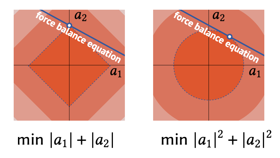
We augment volume with a least-squares visibility penalty. Because $v_{ij}$ is linear in $\sqrt{a_{ij}}$, the squared-visibility cost $\lambda g_{ij}^2 a_{ij}$ stays linear in the unknown areas and fits inside the same linear program.
Unknowns are rod/wire areas $\mathbf{a}$, axial forces $c_{ij}$, and shear forces $\mathbf{q}_{ij}$ coupled through yield-stress inequalities. Each rigid object must satisfy force balance $\sum \mathbf{f}_i = m_k \mathbf{g}$ and torque balance $\sum (\mathbf{x}_i - \bar{\mathbf{x}}_k) \times \mathbf{f}_i = \mathbf{0}$. We solve with Mosek; typical scenes take under a minute after visibility precomputation.
The weight $\lambda$ trades material volume against visibility (we used $\lambda = 10{,}000$ in the paper examples). A linearized shear model lets thin rods resist bending without breaking convexity.
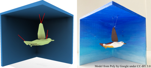
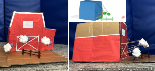
Traversing the viewpoint distribution shows supports staying tucked behind occlusions. The bunny-and-teapot scene demonstrates multi-object equilibrium; the sheep uses separate rod and wire graphs with different material limits.
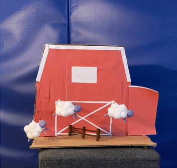
We validated the method by fabricating several scenes — 3D-printed attachment points, hand-assembled rods and wires, and real objects held in mid-air.
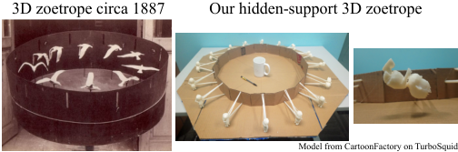
Levitating objects show up everywhere in physical stories — museum dioramas, theatre sets, promotional displays, and animation. Stop-motion and zoetropes are especially unforgiving: if a character is mid-air, the support rod is visible in every frame unless you hide it.
I used this method in my PhD zoetrope work — generating per-frame hidden supports so a backflipping character and a pancake both appear to float, then hiding those rods from the camera's viewpoint.
Project page · Eurographics 2021 paper · ArXiv · Supplemental video · PhD thesis (Ch. 1)
